Coche radio control

Paso 1: Piezas para imprimir
Encuentra todas las piezas que necesitas en Thingiverse
https://www.thingiverse.com/thing:3669829
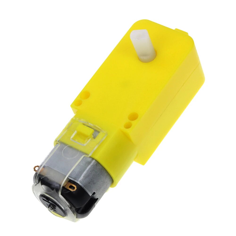
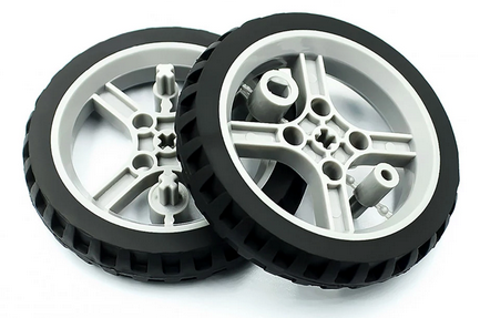
Yo no he impreso las ruedas, he adapatado unas ruedas de servos 360 con motores CC.
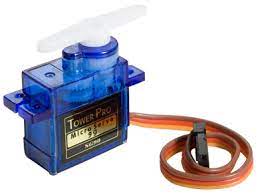
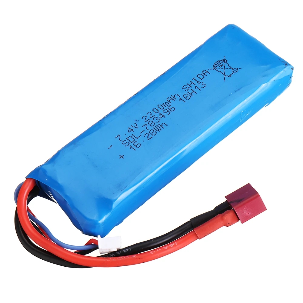
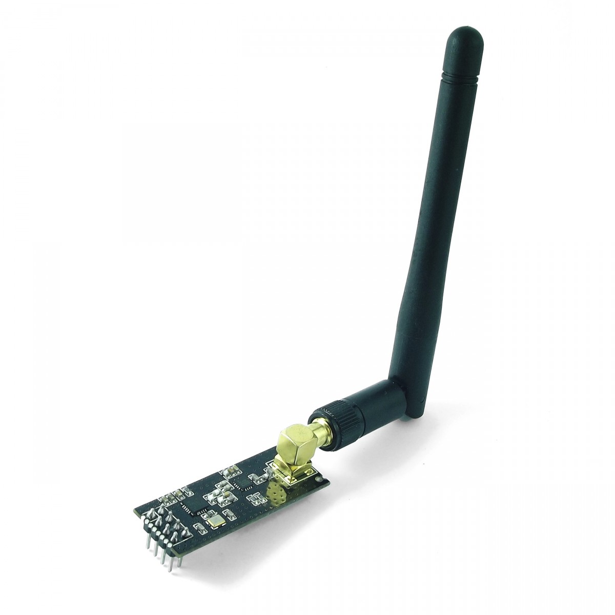
Paso 2: Piezas necesarias.
Aquí está la lista con todas las piezas necesarias para el triciclo.
 |
|
 |
|
 |
|
 |
|
 |
|
 |
|
 |
|
 |
|
- 16 imanes de 6 mm x 3 mm
- 2 rodamientos de 12 mm x 8 mm x 3,5 mm
- 2 rodamientos de 10 mm x 5 mm x 4 mm
- tornillos M2 x 4 mm, 8 mm, 10 mm, 12 mm y 25 mm
- 4 tornillos de cabeza semiesférica M3 x 25 mm y 14 mm
Puedes ver el montaje en el siguiente enlace de instructables, ya he modificado alguna pieza por tener una ruedas distintas y utilizar otra cámara.
https://www.instructables.com/RC-Trike-With-Rear-Steering-Wheel/
Chasis con modificaciones para los motores
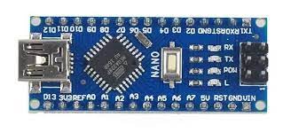
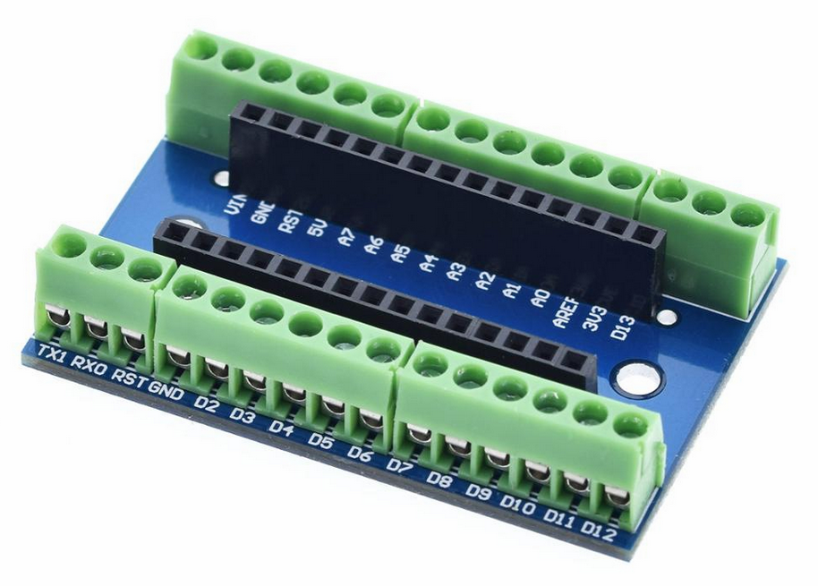
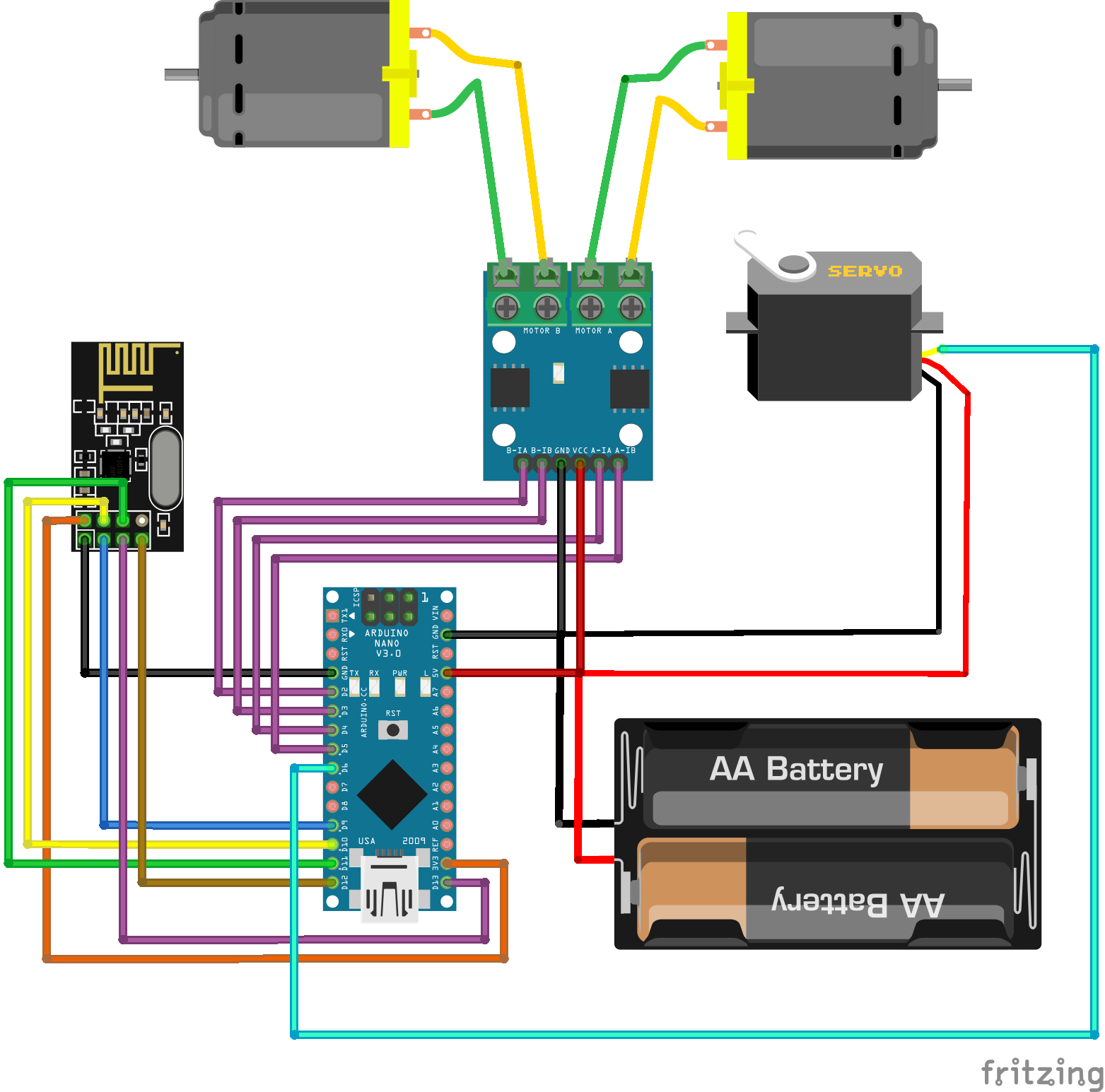
Esquema de conexiones:
Para el receptor:
// Librerías
#include <RF24.h> // Driver de Radio - Módulos nRF24L01+
#include <Servo.h>
// Pines RF24L01
#define PIN_CE 7
#define PIN_CSN 8
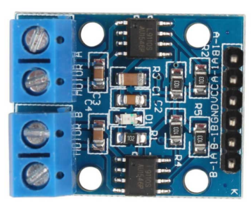
// Pines L9110
#define PIN_M1A 2 // B1-A
#define PIN_M1B 3 // B1-B
#define PIN_M2A 4 // A1-A
#define PIN_M2B 5 // A1-B
// definimos el servo dirección
#define PIN_SERVO 6
Servo myservo;
// Canal de Comunicaciones nRF24L01+ [ 0 .. 125 ]
// TODO: Averiguar el valor óptimo | Selección automática
#define CANAL 124
// ID de Enlace Emisor + Receptor
#define ID_ENLACE 12345 // Tipo int de 16bits
// Retardo de Bucle - ms
// TODO: Averiguar el valor óptimo
#define RETARDO 100
// Instanciación Objeto RF24
RF24 radio(PIN_CE, PIN_CSN);
// Selección de Canal
// TODO: Averiguar el valor óptimo
const byte ADDRESS[6] = "TRICI";
// Estructura de Datos
// TODO: Reconsiderar Codificación de Botones
struct {
int id;
char btnA;
char btnB;
char btnC;
char btnD;
char btnE;
char btnF;
char btnK;
int xAxis;
int yAxis;
} data;
// Velocidad Actual de los Motores
int velocidad = 0;
// Delta de Giro
int giro = 0;
// Configuración
void setup() {
// Configuración - Pines l9110
pinMode(PIN_M1A, OUTPUT);
pinMode(PIN_M1B, OUTPUT);
pinMode(PIN_M2A, OUTPUT);
pinMode(PIN_M2B, OUTPUT);
myservo.attach(PIN_SERVO);
// Configuración Consola - Depuración
Serial.begin(9600);
// Inicializa Sistema RF sobre el bus SPI
if (!radio.begin()) {
Serial.println(F("¡¡¡El Hardware de Radio no responde!!!"));
while (1) {
} // Bucle infinito
}
// Selección de Canal
radio.setChannel(CANAL);
// Nivel de Potencia Sistema RF: MIN | LOW | HIGH | MAX
// LOW: Minimizar problemas alimentación
radio.setPALevel(RF24_PA_HIGH);
// Velocidad de Transmisión
// radio.setDataRate(RF24_250KBPS);
radio.setDataRate(RF24_2MBPS);
// Save on transmission time by setting the radio
// to only transmit the number of bytes
// we need to transmit
radio.setPayloadSize(sizeof(data));
// Modo Lectura > Pipe 1 + Dirección
radio.openReadingPipe(1, ADDRESS);
// Sistema RF en Recepción - RX Mode
radio.startListening();
}
void loop() {
// Enlace TX / RX
boolean radioOK = radio.available();
// Datos Recibidos > Sistema RF
if (radioOK) {
// Leer Datos > Estructura
radio.read(&data, sizeof(data));
// Depuración - Datos recibidos
Serial.print(F("ID: "));
Serial.print(data.id);
Serial.print(F(" - X:"));
Serial.print(data.xAxis);
Serial.print(F(" - Y:"));
Serial.print(data.yAxis);
Serial.print(F(" - "));
Serial.print(data.btnA);
Serial.print(data.btnB);
Serial.print(data.btnC);
Serial.print(data.btnD);
Serial.print(data.btnE);
Serial.print(data.btnF);
Serial.print(data.btnK);
Serial.println();
// Retardo Mostrar Mensajes
delay(RETARDO);
}
else {
Serial.println(F("¡¡¡Sistema RF no disponible!!!"));
// Retardo Separación de Datos
delay(RETARDO);
}
// Maniobras
if (radioOK && data.id == ID_ENLACE) {
// Eje Y - Adelante | Atrás
if (data.yAxis < 470) { // 470 - Atrás
// yAxis [470..0] > PWM Speed [0..255]
velocidad = map(data.yAxis, 515, 0, 0, 255);
retroceder(velocidad);
Serial.print("Atras a velocidad :");
Serial.println(velocidad);
}
else if (data.yAxis > 550) { // 550 - Adelante
// yAxis [550..1023] > PWM Speed [0..255]
velocidad = map(data.yAxis, 525, 1023, 0, 255);
avanzar(velocidad);
Serial.print("Avanza a velocidad :");
Serial.println(velocidad);
}
else
{ // Motores Parados
// Eje Y - En el medio > Motores Parados
velocidad = 0;
parar();
Serial.println("Esta parado");
}
// Eje X - Izquierda | Derecha
// xAxis [0..1023] --> Valor [0..180] grados
giro = map(data.xAxis, 1023, 0, 160, 20);
timon(giro);
Serial.print("Estado del timón :");
Serial.println(giro);
}
}
void avanzar(int velocidad) {
analogWrite(PIN_M1A, 0);
analogWrite(PIN_M1B, velocidad);
analogWrite(PIN_M2A, 0);
analogWrite(PIN_M2B, velocidad);
}
void retroceder(int velocidad) {
analogWrite(PIN_M1A, velocidad);
analogWrite(PIN_M1B, 0);
analogWrite(PIN_M2A, velocidad);
analogWrite(PIN_M2B, 0);
}
void timon(int grados) {
myservo.write(grados);
}
void parar() {
analogWrite(PIN_M1A, 0);
analogWrite(PIN_M1B, 0);
analogWrite(PIN_M2A, 0);
analogWrite(PIN_M2B, 0);
}Ahora vamos con el emisor:
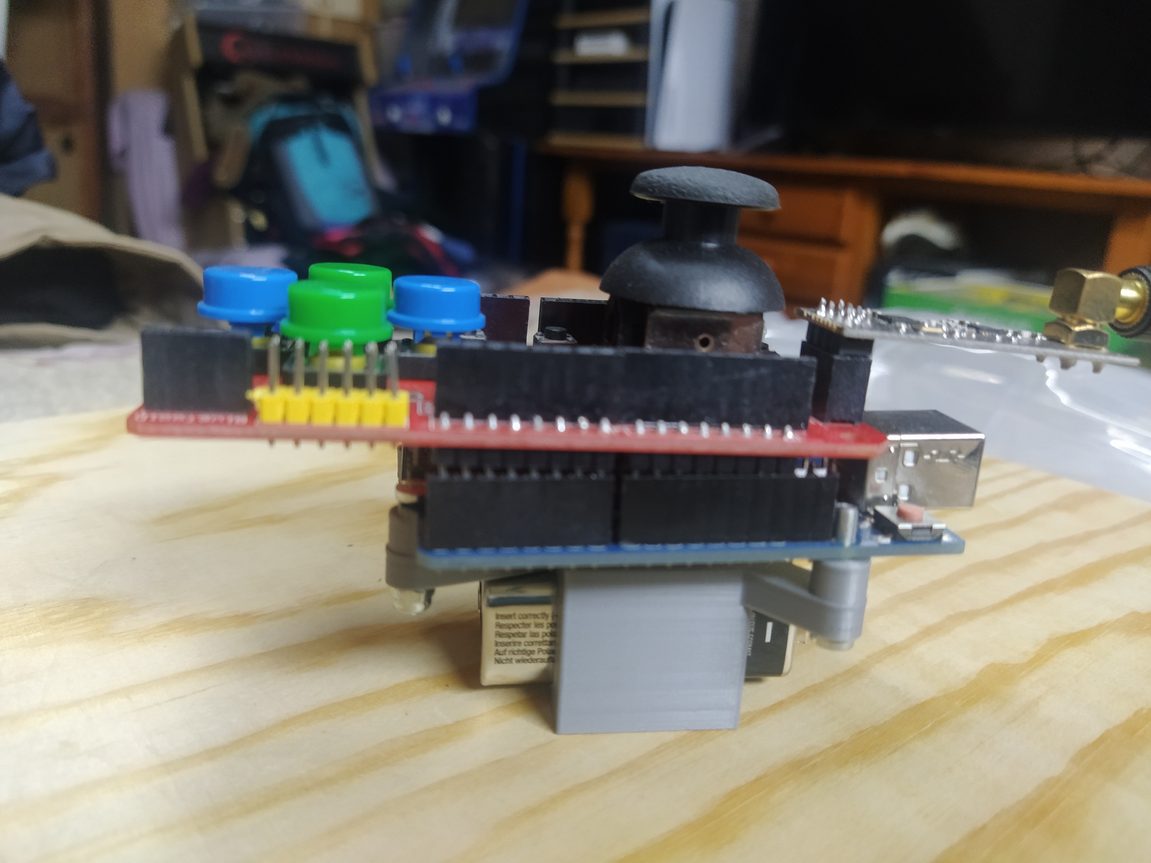
Puedes consultar el funcionamiento de este shield en una entrada de esta web:
Arduino Joystick Shield Nrf24l01 Wireless
La única diferencia será la información que enviamos, en el ejemplo de la entrada anterior detectamos si el joystick está hacia arriba, abajo,… en esta queremos saber en que posición exacta está, para determinar la velocidad y el grado de giro.
El código quedará así:
// Librerías
#include <RF24.h>   // Driver de Radio - Módulos nRF24L01+
//#include <SPI.h>    // Incluida en RF24.h

// ---

// UNO + JoyStick Shield 1.A - Pines Dirección
#define PIN_A   2   //  4 - D2
#define PIN_B   3   //  5 - D3
#define PIN_C   4   //  6 - D4
#define PIN_D   5   // 11 - D5

// UNO + JoyStick Shield 1.A - Pines Control
#define PIN_E   6   // 12 - D6
#define PIN_F   7   // 13 - D7

// UNO + JoyStick Shield 1.A - Pin   Joystick
#define PIN_K   8   // 14 - D8

// UNO + JoyStick Shield 1.A - Pines Ejes X + Y
#define PIN_X   A0  // 23 - A0
#define PIN_Y   A1  // 24 - A1

// UNO + JoyStick Shield 1.A - Pines RF24L01
#define PIN_CE   9  // 15 - D9
#define PIN_CSN 10  // 16 - D10

// ---

// Velocidad Comunicación Serie - bps
#define SERIE 9600

// Canal de Comunicaciones nRF24L01+ [ 0 .. 125 ]
// TODO: Averiguar el valor óptimo | Selección automática
#define CANAL 124

// ID de Enlace Emisor + Receptor
#define ID_ENLACE 12345  // Tipo int de 16bits

// Semáforo de Depuración
#define DEPURACION true

// Retardo de Bucle - ms
// TODO: Averiguar el valor óptimo
#define RETARDO 0

// ---

// Instanciación Objeto RF24
RF24 radio(PIN_CE, PIN_CSN);

// Selección de Canal
const byte ADDRESS[6] = "TRICI";

// Estructura de Datos
// TODO: Reconsiderar Codificación de Botones
struct {
  int id;
  char btnA;
  char btnB;
  char btnC;
  char btnD;
  char btnE;
  char btnF;
  char btnK;
  int xAxis;
  int yAxis;
} data;

// Configuración
void setup() {
  // Configuración Pines Botones
  pinMode(PIN_A, INPUT_PULLUP);
  pinMode(PIN_B, INPUT_PULLUP);
  pinMode(PIN_C, INPUT_PULLUP);
  pinMode(PIN_D, INPUT_PULLUP);
  pinMode(PIN_E, INPUT_PULLUP);
  pinMode(PIN_F, INPUT_PULLUP);
  pinMode(PIN_K, INPUT_PULLUP);

  // Configuración Pines Ejes
  pinMode(PIN_X, INPUT);
  pinMode(PIN_Y, INPUT);

  // ---

  // Configuración Consola - Depuración
  // TODO: Averiguar el valor óptimo
  Serial.begin(SERIE);

  // ---

  // Inicializa Sistema RF sobre el bus SPI
  // radio.begin();
  if (!radio.begin()) {
    Serial.println(F("¡¡¡El Hardware de Radio no responde!!!"));
    while (1) {} // Bucle infinito
  }

  // Selección de Canal
  radio.setChannel(CANAL);

  // Nivel de Potencia Sistema RF: MIN | LOW | HIGH | MAX
  // LOW: Minimizar problemas alimentación
  // TODO: Averiguar el valor óptimo
  radio.setPALevel(RF24_PA_HIGH);

  // Velocidad de Transmisión
  // TODO: Averiguar el valor óptimo
//  radio.setDataRate(RF24_250KBPS);
  radio.setDataRate(RF24_2MBPS);

  // Save on transmission time by setting the radio
  // to only transmit the number of bytes
  // we need to transmit
  radio.setPayloadSize(sizeof(data));

  // Modo Escritura ( Siempre Pipe 0 ) > Dirección
  radio.openWritingPipe(ADDRESS);

  // Sistema RF en Emisión - TX Mode
  radio.stopListening();

  // ---

  // Establece la ID de Enlace Emisor + Receptor
  data.id = ID_ENLACE;
}

void loop() {
  // Estado Eje X
  data.xAxis = analogRead(PIN_X);

  // Estado Eje Y
  data.yAxis = analogRead(PIN_Y);

  // Estado Botones
  data.btnA = digitalRead(PIN_A) ? 'a' : 'A';
  data.btnB = digitalRead(PIN_B) ? 'b' : 'B';
  data.btnC = digitalRead(PIN_C) ? 'c' : 'C';
  data.btnD = digitalRead(PIN_D) ? 'd' : 'D';
  data.btnE = digitalRead(PIN_E) ? 'e' : 'E';
  data.btnF = digitalRead(PIN_F) ? 'f' : 'F';
  data.btnK = digitalRead(PIN_K) ? 'k' : 'K';

  // Depuración - Datos a enviar
  if (DEPURACION) {
    Serial.print(F("ID: "));
    Serial.print(data.id);
    Serial.print(F(" - X:"));
    Serial.print(data.xAxis);
    Serial.print(F(" - Y:"));
    Serial.print(data.yAxis);
    Serial.print(F(" - "));
    Serial.print(data.btnA);
    Serial.print(data.btnB);
    Serial.print(data.btnC);
    Serial.print(data.btnD);
    Serial.print(data.btnE);
    Serial.print(data.btnF);
    Serial.print(data.btnK);
    Serial.println();
  }

  // ---

  // TX Datos ( Necesita RX Hand-Shake )
  bool envioOK = radio.write(&data, sizeof(data));

  // Depuración - Status Comunicación
  if (DEPURACION) {
    if (envioOK) {
      Serial.println(F("Dato SI enviado"));
    } else {
      Serial.println(F("Dato NO enviado"));
    }
  }

  // ---

  // Retardo entre TX - ms
  delay(RETARDO);
}